Can CADCraft Do 3D? Modeling, DWG Solids, and STL Explained
CADCraft 3D support in v0.17.0: distinguish 3D entities from solid modeling, understand SOLID and 3DPOLY, and plan a DXF-to-3D-printing workflow.
 CADCraft AI Editorial
CADCraft v0.17.0 is useful for 2D drafting and contains some 3D entity support, but it is not yet a complete 3D solid modeler or an STL exporter. A 3DPOLY command, a ViewCube, or “2D and 3D” in a product description does not establish a working sketch → extrusion → solid → printable mesh pipeline.
If your goal is a floor plan, a dimensioned part drawing or a profile for cutting, CADCraft fits that drawing-first workflow. If your goal is a physical part from a 3D printer, you need an additional modeling and export step.
Checked on 4 November 2026 against CADCraft v0.17.0, its command implementations and file-format documentation. cadcraft.org is an independent guide, not the upstream ArtCraft product site.
Three different meanings of “3D support”
The phrase is too broad to answer a practical question on its own:
- Storing 3D information. An entity can have X, Y and Z coordinates, an elevation or a normal vector.
- Editing a 3D model. You can create volumes, change their shape, orbit them, and inspect intersections and faces.
- Delivering a 3D file. You can export a usable solid or mesh in the format another program needs, such as STEP or STL.
A program can implement part of the first without completing the other two. CADCraft's source makes that distinction visible: 3DPOLY stores 3D points through its structured command interface, while the interactive implementation accepts planar point input. Its SOLID command fills triangles and quadrilaterals in a drawing.
Neither fact should be inflated into a promise that an AutoCAD-style EXTRUDE workflow or a slicer-ready export is available.
What the checked release supports
| Task | CADCraft v0.17.0 assessment | What that means in practice |
|---|---|---|
| Draw a dimensioned 2D profile | Supported drafting workflow | Useful for outlines, hole positions and drawings |
| Represent 3D polylines | Present in the command implementation | Coordinates alone do not create a solid |
Use SOLID to fill an area | Present, as a 2D command | A filled face has no modeled thickness |
| Use a complete solid-modeling workflow | Still listed among the project's gaps | Do not plan an extrusion-and-Boolean job around it |
| Import or export STL, STEP or IGES | Not supported in the checked file-format documentation | Use a 3D-capable application for exchange and printing |
| Open a DWG that contains 3D or custom objects | Depends on the entity and read path | Opening the file does not prove those objects can be edited or saved intact |
The repository's roadmap documents are dated and are not a release-by-release certification. This table combines those documents with the tagged source instead of presenting an old feature percentage as a current measurement. Before relying on a later version, check the operation and export format you actually need.
Why SOLID is not a printable solid
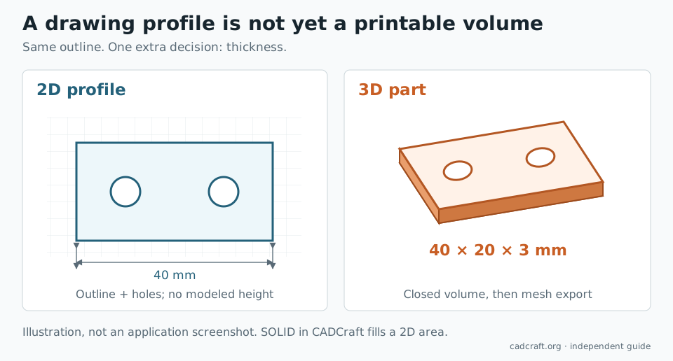
In CAD terminology, names can outlive their original context. CADCraft's SOLID implementation explicitly describes 2D solids: filled triangles and quadrilaterals.
Imagine drawing a rectangle and filling it blue. You now have an area on the page. A 3D printer still needs the missing information: how thick is it, what encloses its sides, and which surfaces define the inside and outside?
The same problem appears if a drawing shows front, top and side views of a bracket. Those views describe a part to a person; they are not automatically connected faces of a digital model. A slicer cannot infer the intended volume merely from the three views.
Why a 3D DWG may look flat or lose objects
A DWG is a container for many kinds of entities. Opening it successfully may mean that the application understood its lines, circles and annotations while preserving, skipping or approximating other records.
Keeping an unsupported object as raw data is different from understanding its geometry. CADCraft's file-format documentation distinguishes modeled entities from unknown records. The tagged save code also warns that some objects cannot be written through a DWG save; even DXF preservation of certain solid records depends on the selected version.
For a mixed 2D/3D drawing:
- Keep the untouched original and work on a copy.
- Identify whether the objects you need are lines and faces, meshes or actual solids.
- Read any warnings when opening and saving.
- Reopen the result in the program that created it, or another application that understands those entities.
A preview that still looks correct is not a full round-trip test. For general drawing exchange, DXF vs DWG covers the two formats; here the extra concern is preserving the model's 3D meaning.
A practical route from a 2D profile to a 3D print
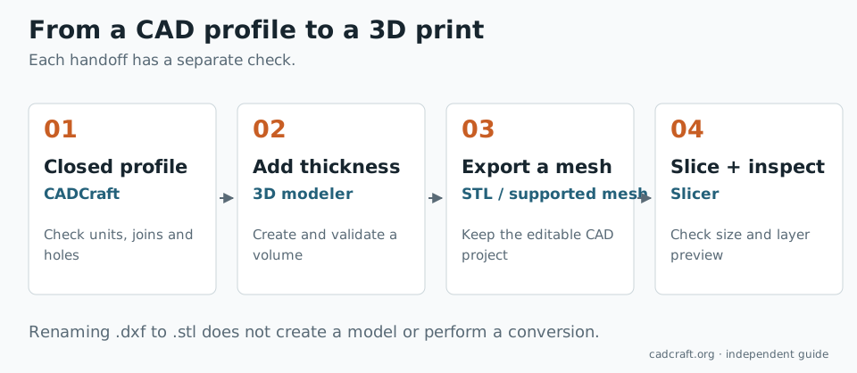
For a flat part with constant thickness, use CADCraft to establish the 2D profile, then use a modeler that can create and export a volume. Do not rename part.dxf to part.stl: changing an extension performs no geometry conversion.
Prepare the profile
Use one closed outer boundary and closed inner boundaries for holes. Remove dimensions, text, duplicate edges and construction lines from the geometry you transfer. Work at a known scale and check a reference length.
A 40 × 20 mm plate with two 6 mm holes is a better first test than an entire floor plan. Decide the third dimension explicitly, for example a 3 mm thickness. That thickness is a modeling decision; it is not contained in the flat outline.
Add volume in a 3D modeler
FreeCAD provides parametric solid modeling and mesh export. Use it to import suitable geometry or recreate a constrained sketch, close the profile, and create the thickness. Check what the import produced before trying to extrude it: a collection of open edges is not yet a closed face.
For a code-driven constant-thickness part, OpenSCAD documents DXF import and extrusion. The basic pattern is:
// Illustrative handoff: profile.dxf must contain suitable closed 2D paths.
linear_extrude(height = 3)
    import("profile.dxf");
That is an OpenSCAD operation, not a command to paste into CADCraft. DXF imports can require cleanup or a compatible export version; test a simple outline first. Keep the original profile and the 3D project's source so you can change the design later.
Export and inspect the mesh
Render or validate the completed solid in the modeler, then export STL or another mesh format your slicer accepts. In the slicer, check the bounding dimensions and the layer preview before printing. A file that opens can still be the wrong size or have missing walls.
An STL contains a triangle mesh rather than the original CAD feature history, and the format does not carry a standard unit declaration. Verify that the example plate arrives as 40 × 20 × 3 mm, not a different unit interpretation. Keep the modeler's editable project as well as the printing file.
What about SolidCraft?
The CADCraft README separately lists SolidCraft, described there as a parametric 3D CAD community application by Tangency Labs. It is a separate project, not an optional CADCraft workspace or the result of selecting a 3D view.
That distinction matters when following release notes or tutorials. A SolidCraft command, supported file format or demonstration should not be attributed to CADCraft without checking CADCraft's own implementation.
Choose by the file you need at the end
Use CADCraft when the deliverable is principally a drawing or a clean 2D profile. Use a solid modeler when the deliverable is a volume, editable 3D part or neutral solid file. Use a mesh export and a slicer check when the next machine is a 3D printer.
For a broader choice of programs, see open-source CAD by task. To check the exact CADCraft release on your machine, use the GitHub and release guide. The Android guide separately covers mobile access; opening CADCraft on a phone does not add a 3D export pipeline.
FAQ
Can CADCraft do 3D modeling?
The v0.17.0 release contains some 3D entity support, including 3D polylines, but it is not a complete solid-modeling workflow. Its documented gaps still include 3D solids, orbit and rendering. Treat it primarily as a 2D drafting tool and verify any specific 3D operation in the release you use.
Can CADCraft export STL files for 3D printing?
STL import and export are not supported in the v0.17.0 file-format documentation checked for this article. Create or transfer the profile into a 3D modeler, give it volume there, and export the resulting mesh for your slicer.
Does the SOLID command create a printable solid in CADCraft?
No. CADCraft v0.17.0 implements SOLID as filled 2D triangles and quadrilaterals. A filled region on the drawing is different from a closed 3D volume or a watertight triangle mesh.
Are CADCraft and SolidCraft the same program?
No. CADCraft is maintained in the ArtCraft organization at storytold/cadcraft. Its README separately links SolidCraft, a parametric 3D CAD community project at tangency-labs/solidcraft. SolidCraft is not a 3D mode that you enable inside CADCraft.